
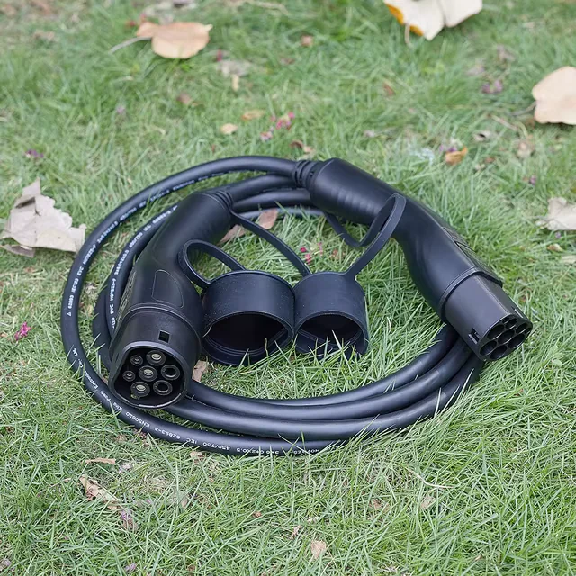
The 30-second answer
AC and DC EV connectors should not be compared by shape alone. The useful procurement question is: where does the technical risk sit, and what evidence proves that the exact purchased configuration controls it?
For an AC assembly, the review usually concentrates on interface compatibility, contact quality, cable construction, temperature behavior, locking, durability and production consistency. A DC assembly can add a wider system boundary: higher-power current paths, temperature sensing, communication-related interfaces and—when the design uses it—cooling hardware and controls.
That does not make every DC connector “better,” nor every AC connector “simple.” It means the evidence pack must match the architecture, rating, duty cycle and market route of the product being purchased.
Buyer rule — freeze the configuration first, then compare evidence. A certificate title, connector family name or successful demonstration cannot replace configuration-level traceability.
This guide is an engineering procurement framework, not product certification or market-entry advice. Confirm the applicable standards, editions and acceptance criteria with qualified specialists for the exact product and destination market.
AC vs DC: compare the risk boundary, not just the plug
The IEC 62196 series separates general connector requirements from dimensional compatibility requirements for AC accessories and the requirements for DC and combined AC/DC vehicle couplers. The current official edition of IEC 62196-1 gives the general framework; IEC 62196-2 addresses AC pin-and-contact-tube accessories; and IEC 62196-3 addresses DC and combined interfaces.
Those documents establish a standards landscape. They do not prove that a supplier's report covers your exact connector, cable, sensing arrangement, cooling option or production revision.
| Validation question | AC connector review | DC connector review | Procurement evidence |
|---|---|---|---|
| Interface fit and retention | Confirm the exact interface, mating compatibility, latch or lock behavior and wear | Confirm the exact DC or combined interface, locking behavior and wear | Drawings, interface definition, test report and controlled sample |
| Current path | Review conductor, termination, contact quality and temperature behavior at the declared configuration | Review the same chain with added attention to high-power current paths and the intended duty cycle | Configuration-specific electrical and thermal evidence |
| Cable system | Check conductor, jacket, bend, strain relief, termination and handling | Check the same factors plus mass, routing and any cooling lines or sensor conductors | Cable specification, assembly drawing and durability evidence |
| Sensing and cooling | Confirm what the design includes; do not infer features from the connector name | Identify sensing architecture and whether the design is naturally cooled or actively cooled | Architecture diagram, control logic description and fault-response evidence |
| Production control | Match the approved sample to bill of materials, work instructions and release tests | Do the same across the larger set of critical components and interfaces | Revision control, traceability and production test records |
The visible interface starts the comparison. The cable, contacts, sensors, terminations and controlled production configuration complete it.
Step 1 — Freeze a configuration identity card
Do not request “the AC report” or “the DC certificate.” Give each candidate assembly an identity card that a quotation, drawing, sample and evidence pack can all reference.
Record at least:
- target market and intended use;
- vehicle interface and mating counterpart;
- declared voltage, current and operating mode;
- cable length, conductor construction and jacket material;
- connector and cable revision;
- locking or latching arrangement;
- temperature-sensing architecture, if present;
- cooling architecture, if present;
- labels, markings and responsible legal entity;
- applicable standards and editions proposed by the supplier.
If one of those fields changes, the buyer should ask what evidence must also change. This single discipline prevents a common failure: a supplier submits a valid document for one variant while the quotation quietly points to another.
For a broader supplier qualification sequence, use the eight evidence gates for portable EV charger OEM sourcing. The same principle applies here: an approved sample is useful only when its configuration can be identified and reproduced.
Step 2 — Review five evidence layers
Layer 1: interface, mating and locking
Start with mechanical compatibility. Confirm the connector definition, mating counterpart, key dimensions, insertion and withdrawal behavior, retention, latch or lock function and the condition after durability testing.
CharIN's connector-test recommendation links the interface review to more than a visual fit check. Its guidance discusses test areas such as mating behavior, locking and connector-related verification under the IEC 62196 framework. Use that as a reminder to request evidence, not as proof for any specific product. See the CharIN recommendation on connector tests.
Stop signal: the supplier cannot state which interface drawing, test sample and production revision belong together.
Layer 2: contact path and temperature behavior
A connector's current path runs through more than the visible contact. Review the conductor, crimp or termination, contact pair, internal joint, cable and any thermal sensing used by the design. Ask how the test configuration represents the offered cable length, conductor, contact revision and duty cycle.
Do not accept a single temperature screenshot as a complete result. A useful record identifies the sample, setup, instruments, ambient conditions, load profile, measurement locations, duration, acceptance criteria and outcome. It should also state what was inspected after the test.
UL Solutions' EV charging infrastructure overview lists different standards for charging equipment and connection devices, including UL 2594, UL 2202 and UL 2251. The procurement lesson is that equipment and connector evidence have defined scopes; one document should not be stretched across unrelated parts of the system. See the UL Solutions EV charging infrastructure standards overview.
Stop signal: a report shows a result but does not identify the offered connector, cable or revision.
Layer 3: cable construction and handling
Cable evidence should connect laboratory performance with the way the assembly will be installed and used. Compare:
- conductor and insulation construction;
- jacket material and environmental assumptions;
- bend and flex expectations;
- strain relief and termination protection;
- torsion or pull risks at the handle and equipment end;
- cable mass, routing and user handling;
- compatibility with the intended storage or cable-management method.
The decision is not “which cable feels thicker.” It is whether the selected construction has documented requirements, a controlled specification and evidence relevant to the intended use.
Stop signal: the cable in the sample, drawing and bill of materials cannot be matched.
Layer 4: sensing, control and cooling boundary
This is where oversimplified AC-versus-DC comparisons often fail.
First, identify the actual architecture. Does the connector contain temperature sensors? Where are they located? Which controller reads them? What happens if a sensor is open, shorted or implausible? Is current reduction handled by the connector, cable assembly, charging equipment or another controller?
Then ask whether the DC design uses natural cooling or active cooling. Not every DC connector is liquid-cooled. If cooling is present, extend the evidence request to the cooling loop, seals, hoses, fittings, coolant compatibility, leak detection, pump or control assumptions, maintenance boundary and fault response.
The 2025 CharIN basic DC EVSE umbrella document is a useful example of system thinking: its checklist includes connector fit and locking as well as interface-specific test reporting. See the CharIN basic DC EVSE document.
Stop signal: the quotation says “liquid-cooled” or “temperature protected,” but no owner, architecture or fault response is defined.
Layer 5: production repeatability and traceability
Qualification is not complete when one engineering sample passes. The buyer needs a path from approved design to shipped unit:
controlled drawing → approved materials → work instruction → in-process checks → final release test → batch record → field trace
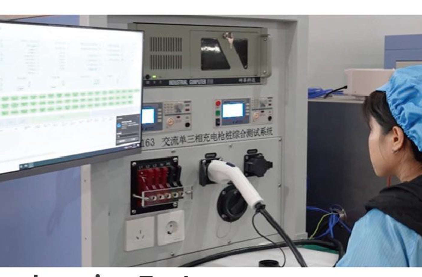
A test bench creates value only when the tested setup, acceptance criteria, result and production unit are linked by traceable records.
Ask the supplier to demonstrate the path on one example serial or batch reference. Trace it backward to critical components and forward to shipment records. Then introduce a hypothetical field fault and ask how the affected population would be identified.
Stop signal: production changes can occur without a documented review of affected evidence.
The buyer's ten-item evidence pack
Request these artifacts before moving from technical discussion to a controlled pilot:
- Configuration identity card for the quoted assembly.
- Interface and assembly drawings with revision status.
- Applicable-standard and edition matrix for the target market.
- Test-report index that maps every document to model and configuration.
- Current-path and thermal-test summary with setup and acceptance criteria.
- Cable specification and termination-control documents.
- Sensing and cooling architecture description, where applicable.
- Durability, environmental and post-test inspection records relevant to intended use.
- Production release-test plan, fixture controls and traceability example.
- Engineering change-notification and approval workflow.
The SUPERGENIE supplier RFQ checklist can help turn this list into an inquiry package. A structured request reduces ambiguous back-and-forth and makes supplier answers easier to compare.
A stop/go matrix for procurement
| Gate | Green | Yellow | Red |
|---|---|---|---|
| Configuration | Quote, sample and documents share one controlled identity | A non-critical field needs clarification | The offered variant cannot be identified |
| Interface | Mating and locking evidence matches the interface and revision | One report mapping is incomplete | Interface or sample differs from the report |
| Thermal/current path | Setup and result match the offered assembly | Duty-cycle relevance needs review | Test conditions or sample identity are missing |
| Cable | Drawing, material and sample match | Handling assumption needs confirmation | Cable construction is uncontrolled |
| Sensing/cooling | Architecture, owner and fault behavior are defined | One control boundary needs clarification | Feature is claimed without design evidence |
| Production | Revision, release test and traceability are demonstrated | Pilot evidence is incomplete | Critical changes can bypass review |
Do not average a red gate into a passing score. A strong result in one layer cannot compensate for an unidentified configuration in another. Resolve the red gate, change the proposed configuration or stop the release.
Questions buyers often ask
Does a higher current rating automatically require liquid cooling?
No universal conclusion should be drawn from the rating alone. Cooling architecture depends on the complete design and intended operation. Ask the supplier to identify whether the offered configuration is naturally or actively cooled and provide configuration-specific evidence.
Is one connector certificate enough for the full charging product?
Do not assume so. A connector document has a defined scope. Charging equipment, protective functions, cables, interfaces and market requirements may involve different evidence. Match every document to the exact product and route.
Can AC and DC suppliers use the same scorecard?
Yes—the five layers remain useful—but the depth and system boundary change. The scorecard should expand where the DC architecture adds sensing, control or cooling interfaces.
What should be checked again after a component change?
Start with impact assessment: identify the affected assemblies, drawings, tests, approvals, labels, production controls and field population. The required retest or review depends on the changed component, applicable route and qualified specialist judgment.
Turn the matrix into a configuration review
When you contact SUPERGENIE, send the configuration identity card with your target market, interface, ratings, cable, sensing or cooling architecture and unresolved evidence questions.
That gives procurement and engineering a concrete starting point: not “AC or DC—which is better?”, but which exact assembly is being purchased, which risks apply, and what evidence closes each one?